Thursday, 9 February 2017

Printable soft circuits for Arduino, Microbit and Raspberry Pi

Image of an embroidered design printed onto cotton
The following idea developed out of a secondary school Creative Computing club I helped run. I had read that one way to engage more girls in coding was with e-textiles so I looked into ways that we could incorporate this into our club.

I have seen some impressive e-textile creations online but many of these involve significantly more sewing than actual coding. I was concerned that by introducing e-textiles to the club we would end up with students spending most of their time sewing rather than forging ahead with more challenging coding concepts.

I wanted something in kit form, with minimal sewing but which introduced students to the potential of e-textiles and soft circuits. It also had to be cheap as we had very little budget. Basically I was after a printable textile equivalent of kits such as this Christmas Tree kit:


Pi Hut's Christmas Tree Kit

or even better, something like this e sewing template from Spark Fun
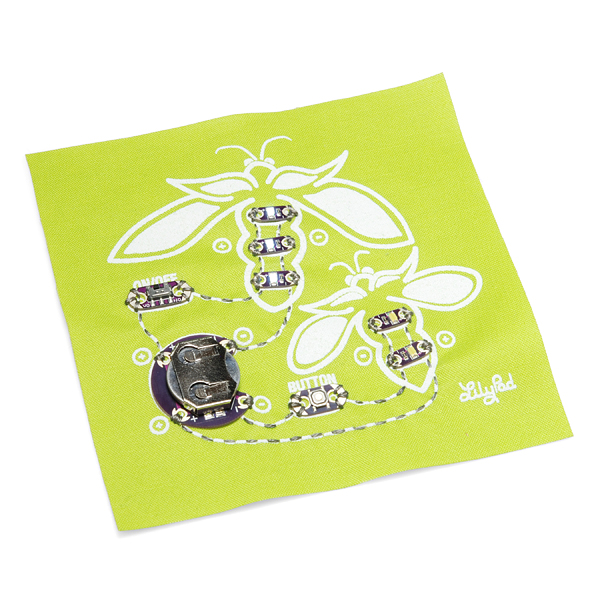
Lilypad e sewing kit
So, I turned to my old friend - a stack of inkjet T-shirt transfer paper - which I have called upon for many projects over the years. I found a suitable Christmas Tree Image online to which I added the following:
  • LED positions
  • resistor positions
  • guidelines for conductive thread
  • external connection positions
The image was then reversed,


printed onto T-shirt transfer paper, cut out and ironed onto white felt. Here is the finished article.

Completed Christmas Tree
I sewed this myself and presented it to the students as one of many ready-made projects for which the coding was the main goal. Another example was this training shoe:

Trainer Light Sequencing Project
And here are a couple connected up to a BBC microbit:


Once completed, these e-textiles were easy to store, reusable and robust.

Not only is this technique useful for introducing e-textiles it also provides an alternative to breadboard circuits and commercially made projects such as traffic light add-ons.

No special electronic components were used, just cheap LEDs and resistors which were attached with conductive thread. There are plenty of instructions elsewhere online as to the best way to sew these on. I use long nose pliers to twist the ends into loops, but scissors also work. Here are some of my efforts:


And for the terminals, I use small coils of copper wire. These can be attached easily to crocodile clips or to jumper wires:


Saturday, 4 June 2016

An Arduino Controlled Cyber Pet


As a volunteer in a creative computing club I was looking for ideas to inspire students and came across a collection of school project kits based on the PICAXE microcontroller.

One of the more interesting projects describes uses of microcontrollers in popular cyber toys such as the Furby. Here are some extracts from the manual for that project:


the inner workings of a Furby


Although we were working with Arduinos, much of the information provided for PICAXE microcontrollers applies equally to the Arduino and this looked like an excellent project to inspire my students.

And for anyone looking for clear descriptions of basic electronic components and microcontroller interfacing circuits the PICAXE manuals are brilliant.

So, I set about creating a cyber pet of my own using the components we were teaching the students about and the craft materials we had available. For the body of the pet I used a cheap soft toy dog (from a charity shop). Here is a video of the finished result:


The following components were used:

  • 2 LEDs for the eyes
  • 1 reed switch in the nose
  • 1 light emitting diode (LDR) in the head
  • 1 servo motor mounted on k'nex in the body
  • 1 piezo module attached directly to the Arduino
  • several resistors
The arduino and battery pack were hidden in the body.

As I had not soldered before I chose to use conductive thread to attach and link components.

LEDs, resistors, LDR and the reed switch were all attached to the inside of the head with conductive thread which was then attached to insulated wires. This required some thought in order to avoid short circuits. All of the sewing was within the head of the toy which was filled with stuffing. The circuit was planned out in advance of any sewing with components being added gradually and tested as I went along: 

planning out the circuit

The servo motor was mounted on a k'nex structure. This required creating extra screw holes in two orange pieces of k'nex. A lolly stick was attached to the servo arm to provide a mechanism for moving the head. 
k'nex motor support
Servo motors are great for beginners as they contain their own driver and can be connected directly to the Arduino. The motor I used was a tiny towerPro SG90; these are available very cheaply. The disadvantage of servos is that most are not continuously rotating, but for projects such as this they are perfect.

The finished cyber pet was used as a demo when introducing students to the project part of the club. I had also picked up a couple of Furbys in a charity shop as examples of very sophisticated commercially available cyber pets, but which included many of the components we were learning about:

demo furby

dissected furby
This turned out to be a popular choice of project for the students over the last few weeks of the club. Unfortunately time was very limited and most students only got as far as adding a motor to their own soft toys (enabling them to wag tails, nod heads etc.) but they all enjoyed the experience and hopefully got a feel for how commercial toys are developed.

Sunday, 3 April 2016

Creative Computing with the Arduino - experiences of a school club

Last year I volunteered on a Creative Computing project with Science Oxford. Myself and a fellow STEM ambassador ran a lunchtime club in a local secondary school with kit kindly donated by The Royal Academy of Engineering.


First Time Experiences

The first week was about getting to grips with the arduino, a breadboard and a simple LED circuit.


The Blink Circuit


The Blink Sketch

For the next few weeks we introduced basic programming concepts and a few simple electronic components. This was very successful, with most students being able to complete the weekly set task within the short lunch break.


Simple Tone Generator


For the final few weeks we encouraged the students to work on a project of their own, using the programming concepts and components they had learned about. We gave them a few ideas and lots of craft materials to work with. This was based on the success of a few workshops that had been run previously in the school holidays.


Animating a soft toy

In terms of production, the project weeks were less successful, with few students completing anything they set out to achieve. I think the main reasons for this were:
  • time required for setting up and tidying away eating into useful project time
  • C/C++ being a difficult language for beginners
  • wider mix of abilities and ages compared to the holiday clubs
  • our inexperience of teaching
  • too many different projects on the go at once, too much freedom
  • students preferring to spend time constructing the craft element, rather than doing any programming
This was a little disheartening. However, the school was delighted with our efforts and we were invited back to run a second club. I was pleased to see some of the original students returning for more in addition to several new faces.

However, we were now faced with the problem of some students being total beginners and others having already done the taught part of the club. In addition, we wanted to improve on the less successful 'project' part of the club.

Improving Our Efforts

We decided to stick with the taught part. But for the project weeks I devised a number of ready made projects complete with guidelines on connecting and programming (but not full solutions). Students who had been with us before were allowed to work on the projects from the first week or re-do any parts of the taught weeks.


trainer light sequencing

plush toy mood lamp

This worked well on the whole, and was much better than the free for all of the first club. The ready made projects were less of a step up from the taught component of the club and students had more of a sense of achievement at the end. In addition, managing students working on familiar projects was a lot easier, particularly as I was the only STEM ambassador available for much of this club. It also meant we didn't have to store several crates worth of craft materials.


In Conclusion


This was a very rewarding experience but I did feel that the weekly sessions were too short and that this would have been better run as a series of after school workshops (maybe 2 hours each session). Having to disconnect everything at the end of a session was frustrating. Just getting a student back to where they had been the week before could take up half the session. And they had to eat their lunch whilst at the club.

However, I was very impressed with the robustness of the Arduinos as they certainly were not treated with kid gloves! Not one of them failed. But the programming language (C/C++) proved too much for many students, especially as few had programmed before (not even in Scratch). 

What Next?

The BBC recently launched the micro:bit:


I am looking forward to when the micro:bit becomes available to the general public and hope to adapt some of the Arduino projects that came out of this club. From what I can see, it will be a much easier platform to get started with compared to the Arduino.


Wednesday, 14 January 2015

Keeping my Joggler going with the new Tesco API

Joggler - an organiser for busy families


Back in 2009, O2 launched the Joggler. The adverts caught my eye and the product looked interesting (this was before the days of the Ipad and other such tablets). But at close to £150 I was not prepared to buy one. Nor were many other people it would seem as a year later the price dropped drastically to £50 and O2 sold off the remaining stock. At this point, I bought one on ebay and it has lived in my kitchen ever since.
Joggler Squeezeplay - awesome
It is mostly used as a controller for my music system, but its other main purpose has been as a shopping basket for my Tesco account. You see, once the Joggler arrived, I couldn't resist tinkering with it and its arrival coincided nicely with Tesco's launch of its API for third party developers.

Although this was my first experience of a web API and terms like JSON and REST were all new to me, I found the reference guide provided by Tesco to be excellent and knocking up a useable app was a breeze. The hardest part was getting my elderly version of Flash/ActionScript to run on the Joggler, but I got there in the end.
My Joggler App

It was great. When I ran out of something in the kitchen I just tapped on my Tesco favourites and added the item to my basket ready for my next order. This simple app has served me well for the best part of 5 years. As has the Joggler, despite its regular dusting of flour, icing sugar, butter and everything else that has been thrown at it.

But, after the Christmas and New Year break I went to add something to the basket and .... nothing. No service. Now I do vaguely remember reading somewhere that the service was going to be discontinued but .... did nothing.

Fortunately, all is not lost as Tesco appear to have been busy re-branding and the old techfortesco has become
http://www.tescolabs.com/
complete with new API. Yay!

So, I signed up for a dev key, fired up Flash 5 and fixed up my app to access the new API. Fortunately most of the commands that I use (LOGIN, LISTPENDINGORDERS, LISTBASKET, LISTFAVOURITES, PRODUCTSEARCH) all worked seamlessly. CHANGEBASKET however doesn't appear to do anything; the response tells me that 'Basket change completed successfully' but when I request the basket via LISTBASKET, nothing appears to have been added. I have a very vague recollection of this problem happening the first time around. Perhaps it just hasn't been implemented yet. I will wait before investigating my app further, but not for too long as I'm about to run out of tea and I really can't let that happen.

Any sane person may be wondering why I stick with the Joggler. I have asked myself that many a time. In fact, last year, I was all set to replace it with my Asus EEpad with its lovely big screen. However, that died completely after less than two years of ownership and very little use - and it cost about 10 times the price of my trusty old Joggler! So cross. I am reluctant to splash out on another tablet just for the kitchen, especially as it will have to be sticky finger proof, something that thankfully the Joggler has already proved to be.


Thursday, 25 September 2014

Raspberry Pi Robotic Arm

Build Your Own Robot Arm
I came across this bargain a while ago in a local charity shop. Brand new, unopened and just £2.99! I have seen many examples of this kit being hooked up to the Raspberry Pi, so I thought it would be a good opportunity to get physical with my own RPi.

However, the majority of tutorials are based on the USB model. The one I have comes with a simple switch box control, not USB.

So, time to control the motors directly. All five of them.

I read a few tutorials before getting going and soon realised that connecting the motors willy nilly to the GPIO pins was probably not a good idea. There appear to be a number of ways of connecting the motors, but which was going to be best was a bit of a mystery. I plumped for getting started with a L298N H Bridge driver for no reason other than I had seen this working in another blog post and it seemed to be safe and foolproof.

I bought the L298N driver board from ebay but it didn't come with a datasheet. It looks a bit like this one, so I used this as a basis for connecting it up.

L298N motor driver

Although, it is capable of driving two motors, I started out by just trying out the motor controlling the robotic arm jaws.

I hooked up the +ve and -ve leads from the robotic arm battery pack (containing 4 D cells ~ 6V) to the +12V power and power GND terminals. The +5V power terminal was left unconnected - I believe this is an output. I then connected the yellow and black leads from the jaws motor to the output A terminals.

Next, the raspberry pi was connected. One GND pin was connected to the same GND as the robotic arm battery pack. Two GPIO pins (23 & 24) were connected to the two input pins on the driver board corresponding to 'output A'.

Some simple python code was then written to enable the pins, turn the motor clockwise, anti-clockwise and stop. This verified that all connections were working ok.

import RPi.GPIO as GPIO
import time

GPIO.setmode(GPIO.BCM)

# set pins as output
GPIO.setup(23,GPIO.OUT)
GPIO.setup(24,GPIO.OUT)

# spin motor one way for 0.2 seconds
GPIO.output(23,True)
GPIO.output(24,False)
time.sleep(0.2)

# stop the motors for 1 second
GPIO.output(23,False)
GPIO.output(24,False)
time.sleep(1)

# spin motor the other way for 0.2 seconds
GPIO.output(23,False)
GPIO.output(24,True)
time.sleep(0.2)

# stop the motors
GPIO.output(23,False)
GPIO.output(24,False)

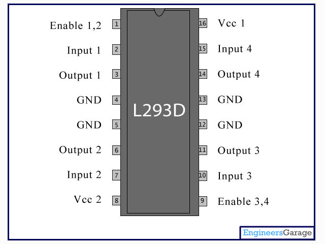
After this success, the other four motors were connected up. One to the other side of the existing L298N driver, two to a separate L298N driver and the final one to a L293D driver. The L293D driver came as just a chip and is not mounted on a board with other components. It looks like this:

L293D motor driver
It is also an H bridge and is capable of controlling 2 motors. I needed a breadboard to mount it and provide easy access to its pins. It was simple to connect up, guided by datasheets readily available online.

I then wrote a python script which allowed the robotic arm to be controlled via keyboard presses (via pygame). The code is available on github robotarm.py

And here is the robotic arm in action:


Great, so I have replaced the perfectly adequate control box that came with the arm with a wiring monstrosity! But the project has lead to a better understanding of interfacing and the research required has pointed me towards many new resources to learn from.

Questions which I now wish to pursue are:

  1. What alternative interfaces could be used to connected a DC motor?
  2. What is an H Bridge?
  3. What are the main differences between the L298N and L293D?
  4. What other motor drivers are popular among robotic enthusiasts?
  5. What other motors are possible?


Sunday, 17 August 2014

Lego WeDo and the Raspberry Pi

After some initial fun with Lego WeDo and Scratch, our enthusiasm waned, mainly due to the necessity to tether any model to our computer. Somehow it didn't seem quite so exciting as Lego Mindstorms where the microcontroller is part of your model giving it the freedom to roam.
Inspired by this Lego / Raspberry Pi model built by another geeky parent I decided to see if we could do something similar. As we already had a WeDo hub, it seemed that would be simpler than getting involved with all that fiddly looking GPIO stuff.

First, the 'car'.

Lego WeDo + Raspberry Pi

Pretty neat eh? The WeDo hub is sitting under the RPi. The black box at the back is not functional; it houses a ridiculously long USB cable which is the only one I have with a slim enough micro USB connector to fit in the PiBow case (my only gripe with this case - others have the same problem). The ribbon cable is not in use.

It was inspired by:

Lego 9719 Robotics Invention System

Lego's early robotic system which housed the processor (RCX) in a box of a similar size to my cased Raspberry Pi. There are lots of archived building instructions for this forerunner to the latest Mindstorms products and we got quite excited about the prospect of adapting more models for the Raspberry Pi.

The Pi itself is housed in a PiBow which is a great case and has the added advantage of a few holes in the bottom which fit perfectly onto Lego bricks. The power source is a Powergen battery pack (as used by 'Geek Dad').

Feeling pleased with myself I knocked together the software. At the time, Scratch only officially supported a single motor, so I decided it was time for my son and me to move onto Python. This was already installed on our Raspberry Pi, but we needed some extra stuff to get it to work with the WeDo hub.
After a few teething problems I managed to install this on our Raspberry Pi. But then we ran into other problems.

First, there are only two USB ports on our RPi. Ideally we needed ports for all of the following:
  • wifi adapter - to login remotely
  • bluetooth adapter - we planned to use the Wii Remote as a controller
  • Lego WeDo hub
I plugged in an unpowered USB hub hoping that would solve the problem. It didn't. Some things didn't work at all, and others were intermittent. Plus, the hub was an added weight for the 'car' to be carrying around.

So, we ditched the Wii Remote idea. 

After booting up the RPi I connected to it remotely over the wifi using Putty from my laptop (I had already noted its IP address from an earlier session). Then I ran the python script remotely. Controlling the car was with a simple character entry interface via Putty. And here we see it in action:


Successfully controlled, but rather slow. The hub can only deliver 5V as opposed to the 9V required by the motors. In addition, even under quite small loads (a ruck in the carpet for instance) the motors sometimes would just stop. The only way to recover was to unplug the Lego WeDo hub, put it back in and restart everything. Not the experience we were hoping for.

I have since tested the Lego WeDo hub on different computers both with Python and Scratch. Whenever two motors are connected it is very easy to stop them functioning by putting them under quite small loads. This has never happened with just one motor attached. I've not seen any reports of this elsewhere, but then not many people are using two motors with it. Perhaps I just have a faulty hub?

Sadly, it is farewell to the simplicity of the Lego WeDo hub for us. Next step is to get to grips with the GPIO pins on the RPi and to get some real power to our motors! 


Friday, 23 November 2012

Fun with Lego WeDo and Scratch

Flushed with the success of reading external inputs from the PicoBoard into our Scratch projects I thought that we would take a look at outputs via Lego WeDo. This is Lego's Junior Robotics system designed for use in schools, but available for home use too. It mainly consists of a motor, a motion/distance sensor, a tilt sensor and a hub to connect to a computer.

Trouble is, at around £80 it's expensive and that does not include Lego's software (but you can use Scratch). The kit does come with instructions for 12 models which make full use of the included motor and sensors, but having taken a look at the plans I thought that my 11 year old son would probably prefer to experiment with his own creations.


Instructions for all of these models can be found at Ro-botica (probably also on the Lego site, but I couldn't see them) . The Ro-botica site is in Spanish, but all instructions are in English.

Besides, we have heaps of Lego at home already, including some older style 9V motors. So, being a cheapskate I opted to just purchase the USB hub for now as really we only want to experiment with motors. Still expensive at around £30 mind you.
The Lego WeDo USB Hub
It arrived and within minutes was connected up to our computer running Scratch. Selecting 'Edit', 'Show Motor Blocks' revealed the following extra blocks in the Motion section.


In order to use these blocks, the WeDo Hub expects a Lego Power Functions motor to be plugged in. But we don't own any. So, what next?

The Power Functions (PF) system is Lego's latest electrical system, replacing the 9V system which was introduced in the 1980s. PF is a four wire system and the older 9V system just used two wires; the connectors are not compatible.

Fortunately, one of the following PF extension cables can act as an adapter between the two systems. This allows older 9V system components to be connected into a PF system.

8886 extension cable 8871 extension cable
The dark grey connector at one end is a standard PF connector. The light grey connector is PF on the top and old 9V on the bottom. So, to connect an old 9V motor to the WeDo hub:

Connect the dark grey connector to the USB hub. And then connect the light grey connector either:

  • directly to the motor (if it has a connector on top like this one)

  • indirectly to the motor via an old 9V cable

  • or indirectly to the motor via an electric plate


Once I had connected the old motor I then played around with the Scratch controls, turning the motor on and off, changing the direction and changing the power. All worked as expected. However, bear in mind that the motor requires 9V to run at full power and the USB hub can only deliver a maximum of 5V.

I then tried a couple of other old 9V Lego components I had:

Electric Light & Sound Bricks: Town Siren + Twin Top Lights
On their own, these did not work when the motor control was activated from Scratch, but with the motor also connected I got sirens, lights and motor spin. And once current was flowing the motor could be taken off and the lights and sirens would remain on.

Now I don't pretend to know exactly what is going on here, but I suspect that the WeDo hub does not allow the current to flow unless there is something to draw enough current attached - maybe? Once current is flowing, you can disconnect the motor and still do things like change direction and power which result in dimming the lights and changing the siren tone. When you 'turn the motor off' from scratch the siren / lights go off and won't come on again without the motor connected.

So next, I thought that I would try putting a resistor in the circuit. I did this by cutting a 9V lead so that one end had the standard connector and the other was just two bare wires:

Adapted cable 5306b
A couple of crocodile clips, a resistor from my kids' snap circuits kit and bingo - lights and siren without the motor connected:


And, using the customised 9V lead, it can be connected to other non-Lego components. I have had success with MES light bulbs and other motors.

Not sure what we are going to do with all this knowledge, but my son has had some fun already. He created this Pirate Ship fairground ride (adapted from the Lego Wedo Ferris wheel instructions) and then I helped him add the lights. Unfortunately it is only possible to control 1 motor circuit from Scratch; I would have liked to have been able to use a separate circuit for the lights.


control for the pirate ship
Conclusions

I am glad that we have had the opportunity to play around with Lego WeDo and I think coupled with the PicoBoard my son can have plenty of fun programming and building. I may now buy a Lego Motion Sensor for him which will bring our total spend up to about £50, so the original £80 set starts to look like a good buy if you also need a motor.

I had hoped that we could use some plans such as from our Lego Inventor - Motion Movers set, but the 5V restriction does not give enough power to drive the models that I have tried so far.

It is a pity that only one motor circuit can be controlled from Scratch. However, it does look like there is a workaround by building a customised Scratch image. Instructions available here on the Scratch Forum, but I haven't tried them yet.

Be careful with any customisations, as I cannot guarantee that any of the above procedures will not damage your USB hub and/or computer.